文档类型 | 文档名称 | 描述 |
认证结果 | 关于化学品的注册、评估、授权和限制 | |
规格书 | ||
样品申请表 | ||
| 快速购买 | ||
特性/Features: | Typical Applications: |
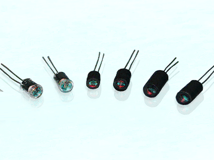
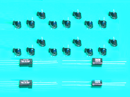
The AOI also uses an optical link between input and output. The input element is an LED and the output element is always a photoconductive cell or, simply a photocell. Together, the coupled pair act as an electrically variable potentiometer. Since the output element of the AOI is a resistor, the voltage applied to this output resistor may be DC and/or AC and the magnitude may be as low as zero or as high as the maximum voltage rating. Because the input will control the magnitude of a complex waveform in a proportional manner, this type of isolator is an analog-control element. AOIs may be used in the ON-OFF mode but the fastest response time is only in the millisecond range. A level-sensitive Schmitt trigger is required between the AOI and logic gates when used in digital circuits.
| Absolute Maximum Ratings @ 25° Maximum Temperatures •Storage and Operating: –40°C to 75°C •Cell Power: 175 mW •Derate Above 30°C: 3.9 mW/°C •LED Current: 40 mA •Derate Above 30°C: 0.9 mA/°C •LED Reverse Breakdown Voltage: 3.0 V | LED Forward Voltage Drop @ 20 mA: 2.0 V (1.65 V Typ.) •5C8 = 2.8 V (2.2 V typ.) •5C9 = 2.8 V (2.2 V typ.) •5C10 = 2.8 V (2.2 V typ.) •Minimum Isolation Voltage @70% Rel. Humidity: 2500 VRMSOutput Cell Capacitance: 5.0 pF •Input/Output Coupling Capacitance: 0.5 pF | ||||||
Analog Optical Isolators—5C Series
Specification Notes:
LED Current: Since the input has a substantially constant voltage drop, a current-limiting resistance is required.
ON Resistance: Dark adapted resistance measured after 24 or more hours of no input.
OFF Resistance: Measured 10 sec. after removal of the input. The ultimate resistance is many times greater than the value at 10 sec.
Response Time: Ascent measured to 63% of final conductance from the application of 40 mA input. The conductance rise time to a specified value is increased at reduced input drive while the conductance decay time to a specified value is decreased. Typical matching and tracking from 0.4 to 40 mA is 25%. Measured 5 sec. after removal of the input. The ultimate resistance is many times greater than the value at 5 sec.
5C9 response times are based on a 2 mA input. 5C10 response times are based on a 10 mA input for ascent time and a 1 mA input for decay time.

Typical Applications of Analog Optical Isolators


